Now that we’re tinkering with rigs that fling things into the air so we can shoot them at 1000 fps (sometimes even more) while following them with the bot, I quickly learned how important it is to have a lot of light. People will tell you, “Hey man, you’re going to need a lot of light if you want anything to look good in (super) slow-motion” and you think, sure we’ll get a few more lights and it will be great. Until I actually started shooting at 1000 fps, I didn’t realize how hard it would be to just keep everything in focus, not to mention looking good at the same time. Our lenses go down to T1.5 but if you do that, the focal plane is so shallow any piece of the product with depth falls out of focus and if it’s moving, the whole shot gets trashed because it’s impossible to keep it sharp.
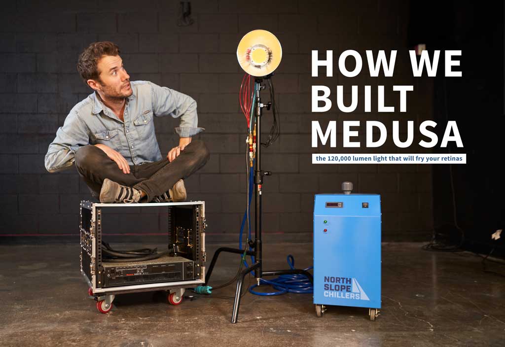
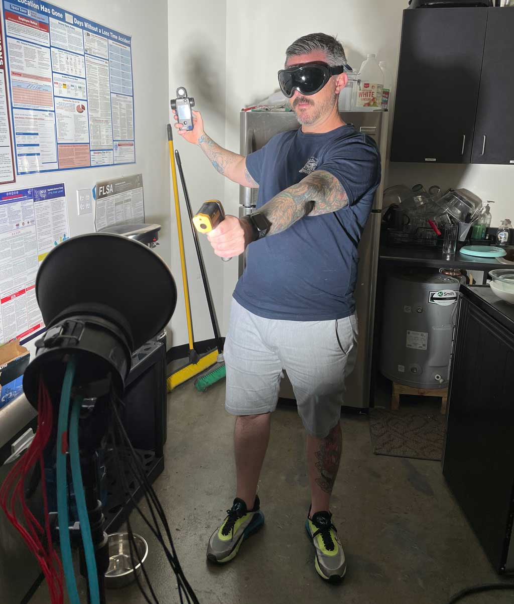
The first test shot with Medusa, our 1500 watt LED hard light.
So I started going down the rabbit hole to see what options are out there for super bright lights. For years, slow-motion shooters have been using these gigantic cinema lights that are about as big as my car and get so hot you can fry an egg in their light path, not to mention the power draw. We have a small space to shoot and even though we do have 3-phase 200 amp power, there’s no way we’d want to use it all up on massive “oven lights” so I started looking into LEDs.
Testing the sync of the donut launch and sprinkle hit.
There are a few super-bright LED (100,000 lumen+) lights that are 95+ CRI on the market but they aren’t cheap, Mole-Richardson makes one but even with a discount it’s over $10k for 1 light. After talking with my friend and collaborator Steve Giralt, I decided to build my own. The idea is to buy all the components online and solder it up myself. I started with a small 100 watt LED that Steve teaches people how to build with his school, The Garage Learning. I’m glad I started small because I smoked my first LED trying to solder it with a crappy soldering iron (not that I can say I’m a great solder-er by any stretch). One of the first tricks I learned is to solder quickly so you don’t heat the LED up too much. When the solder finally stuck and I turned the LED on, it got bright for a few seconds and just burned out. My problem was that the iron didn’t get hot enough to melt the solder quickly. It said it got to 385° but I doubt it did even that. I threw it away and bought a better one. I cranked it up to 750º Fahrenheit and it made all the difference.
After building this little 100-watt spotlight and with the help of our Creative Director Chris Harrelson, we put together a few other lights, framed with gator board cut and taped together and 12 volt light strips. These little guys are a pain to solder but it’s good practice and the lights worked great! To power them we picked up a bench power supply that plugs into the wall (110v) and kicks out up to 40v DC with enough amps to max out many of these stips.
But even with a few more light lights in the studio, we weren’t even close to being able to shoot the slow-motion we wanted. So I looked into the brightest LED COB I could find that was 95+ CRI. The new problem I had to solve is that it needs to be water-cooled and I couldn’t find a cooling block anywhere online that would fit it so I opted to design one myself. With the help of Steve and my friend Buddy Bleckley, I went to work on a 3D design for the LED that would fit perfectly inside Profoto light reflectors that we already had.
After a few back-of-the-napkin drawings based on suggestions from Steve, I hired a CAD engineer to bring it to life. I took the .step files from our engineer and got quotes to have it CNC milled out of solid aluminum. The first few quotes were pretty pricey so we refined our block to use less aluminum and sent it off to be machined. After a few weeks, the cooling block arrived at Bubba’s and I was thrilled. It was crazy to see what looked like a piece from a car engine sitting on my desk, we designed it on a computer and there it was!
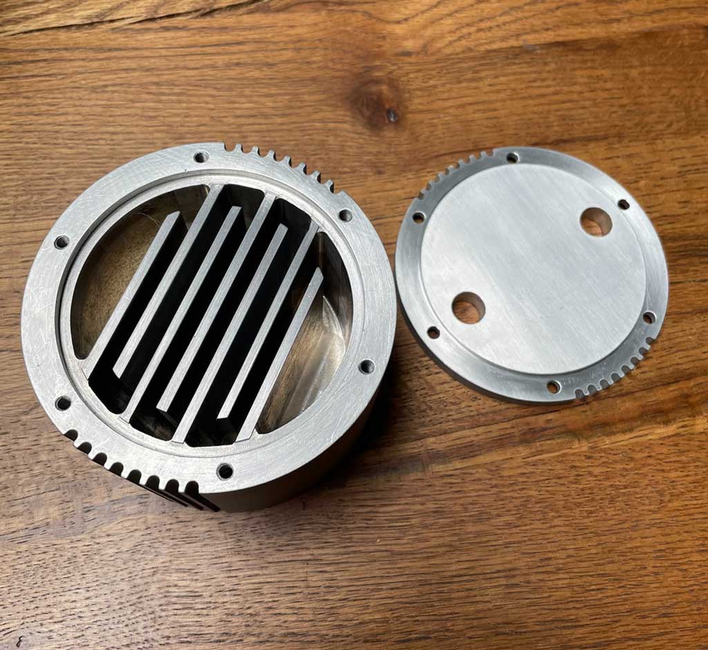
Here’s our water block before cut the gasket and tapped the remaining threads.
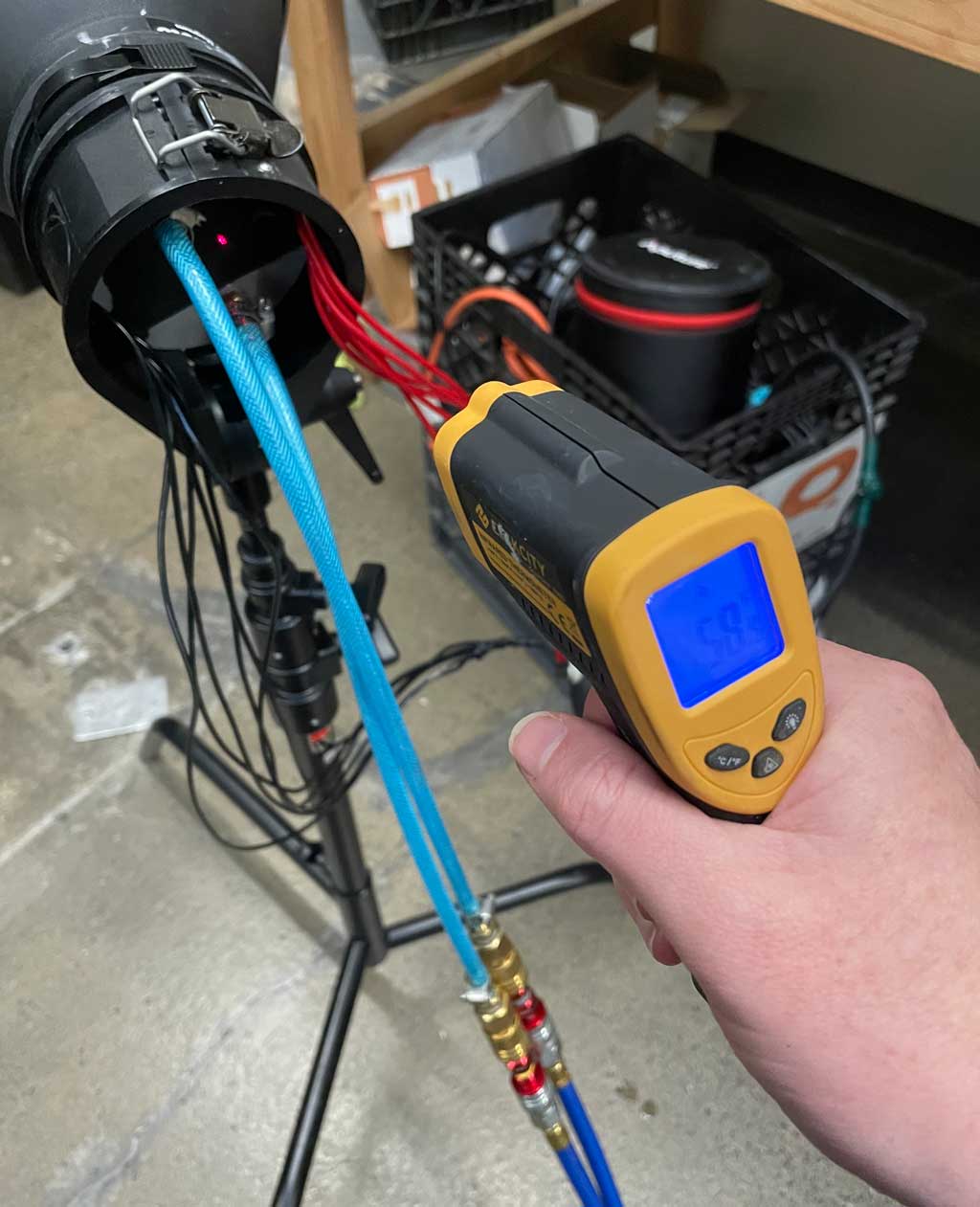
The next step was to have some of the bolt holes threaded. We took it to a machine shop near Buddy’s house in Glendale and the next day it was all ready to be assembled. Originally, when we received the block, most of the holes had threads but some didn’t so I’ll have to figure out why for our next version so they all come threaded. Buddy cut us a gasket with a box cutter and started adding bolts and our air hose valves. We’re using air hoses with quick connects for the chilled water to run through. This was a suggestion from Steve to easily be able to move the light around the studio, remove the hoses and reconnect them quickly. We can also add more lights to the closed-circuit pretty easily.
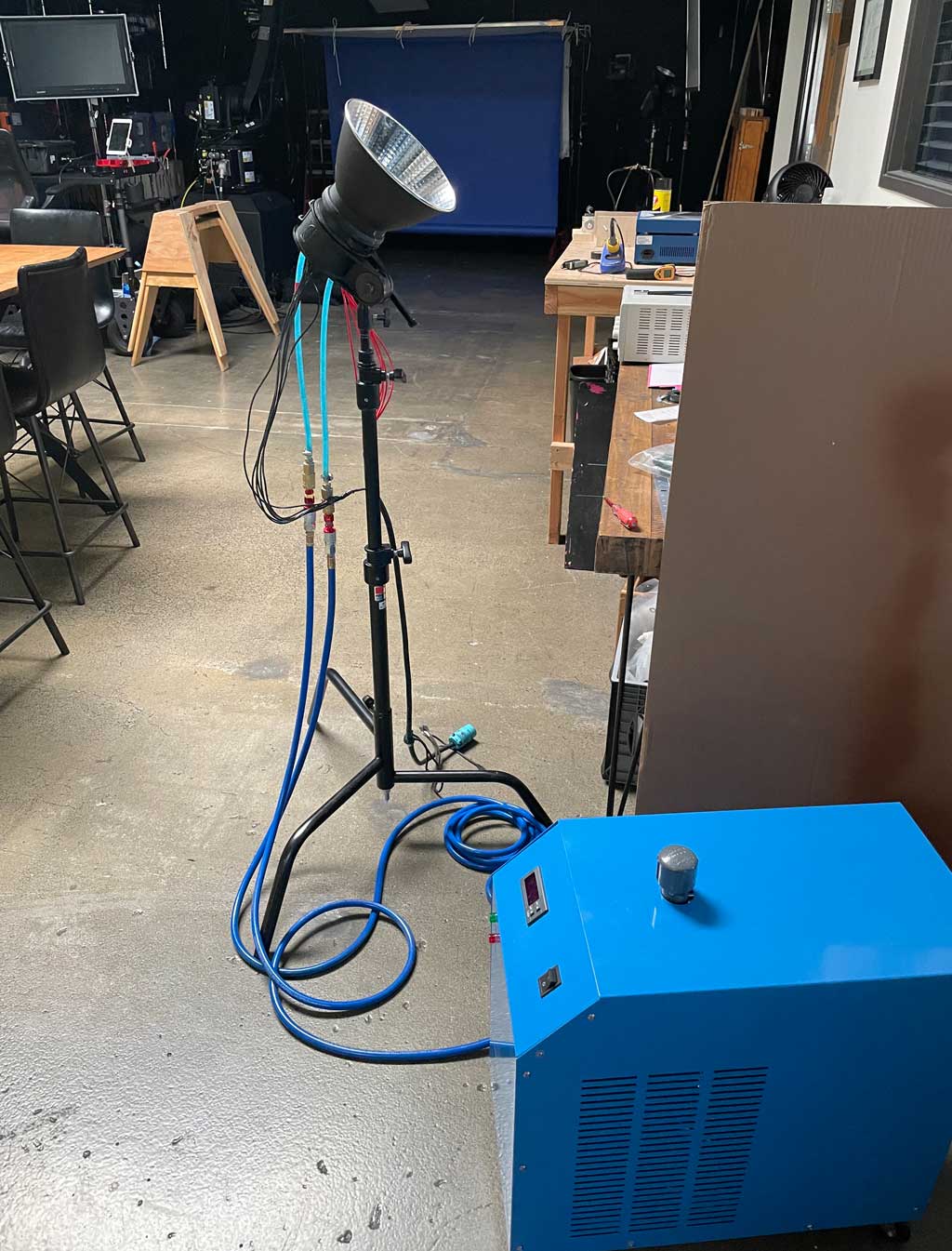
The water chiller was another step we needed to figure out. There are a ton of under-the-sink chillers out there that were cheaper than what we ended up with but I found this small, portable industrial chiller that looked too cool and I figured it would be able to handle several of these lights so there was room to grow with it. It pretty much plugs and plays, I have it set to 45 degrees Fahrenheit and that seems to do the trick. Once we started running the water through our light block it quickly dropped the temperature of the back of the block into the ’50s.
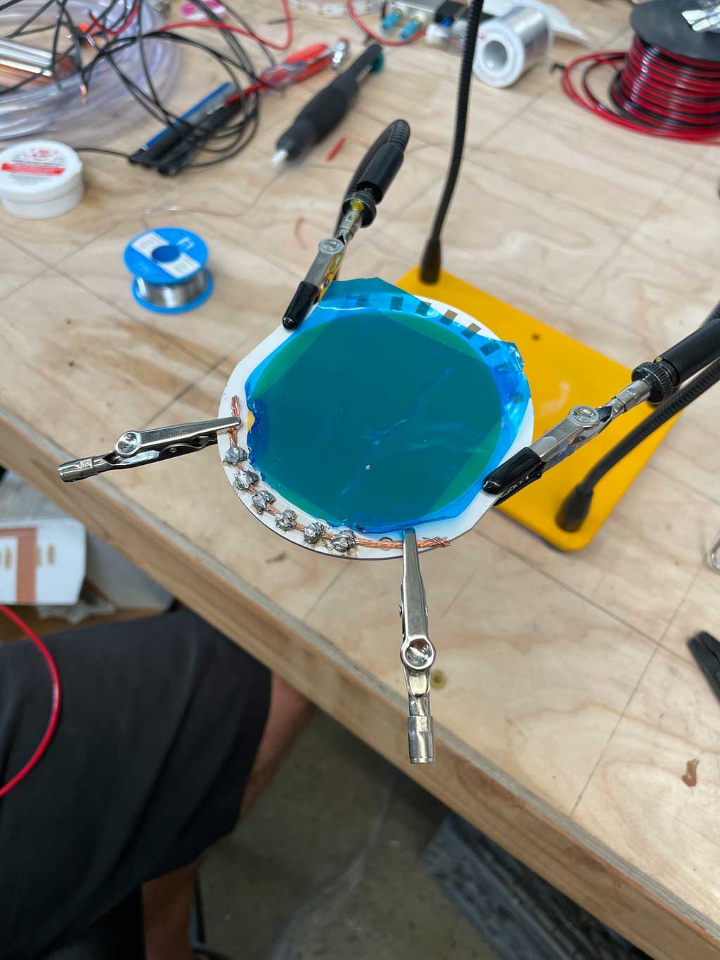
Soldering a wire across all 6 contacts to create a bridge to solder the wires to.
Soldering the wires to the contacts on this LED was a really difficult task. This light is technically a ‘superconductor’ and has been engineered to disperse large amounts of heat, which makes it really hard to solder to. When you’re trying to add solder to the contacts, the solder doesn’t stick because the backing plate is actively cooling the pads, even with our iron at 750º! We ended up having to purchase a thermal plate (basically a hot plate), heat it up to about 200 degrees Fahrenheit, toss the LED on, and solder fast. We did this in steps so we didn’t damage the actual light.
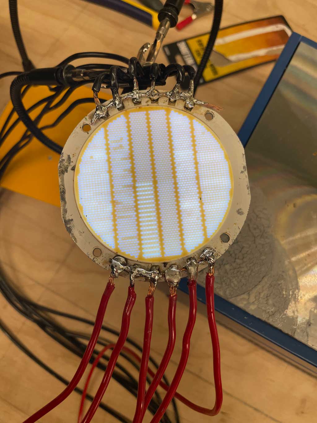
I’m not going to win any awards with my solder job but we got it to work.
It was Steve’s suggestion that we solder a bridge across all the contacts to help bind them together better, which should make for a stronger connection for all of them. It seemed to work really well once we had the thermal plate. Before that, forget about it, there was no way that the solder was going to stick well to the COB.
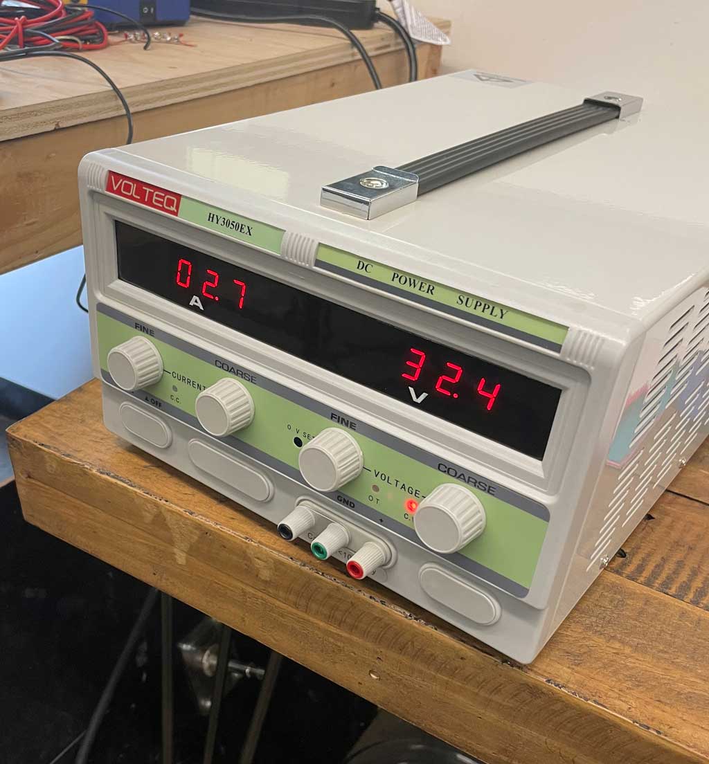
So once we had all of this figured out we needed a power solution to help our little light shine as bright as possible. I started with a power supply that we thought would work but I quickly learned that I wasn’t even close. It was only able to provide 32.5 volts at around 3 amps which is just under 100 watts. Even though this unit should be able to push out 1500 watts it’s not the right configuration for what this COB needs so we had to go on the hunt for a new one.
We really hoped that we could power this light off of one normal 20 amp 110v wall socket but no can do. The next best option, for now, was our 240v 30 amp stove plug. If that worked then we could have another one installed like it in our studio, one could run our robot and the other on these lights. We ended up going with a deck mountable power supply that kicks out 40 volts at 75 amps. Enough juice for 2 of these lights, if it worked. I ordered one online and it was back to waiting on shipping.
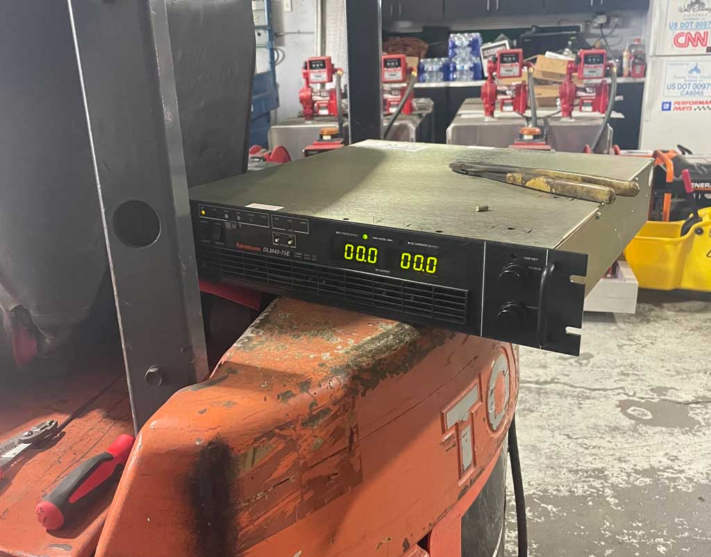
Here’s the power supply sitting on the back of their forklift while they were taking me through it. Thanks, Dave and Matt!
Once it arrived, I brought it to my neighbor’s shop to have them walk me through how it works. We’re starting to get into some serious current here and I really want to make sure that I knew what I was doing and that we’re all being totally safe. My neighbors are amazing and they gladly hooked it up for me and walked me through everything. The cool part was they hooked it up directly to their breaker box so I could easily see how it was powered with a 3-phase hookup.
Now that I had a bit more confidence with this thing, it was time to head back to Bubba’s and plug it in. The only issue here is that even though we have 3-phase power, we don’t have a plug for it yet in our studio, it’s a long story but for now, I had to try to set it up on single phase 240v which the manual said was possible so I gave it a go. This included me going to Home Depot and building a 240v 3-wire plug and it worked!
I can’t tell you how exciting it was to see our light turn on! We slowly stepped up the volts and the amps until we were just under full power checking the temp on the LED throughout. We stopped just under full power, I didn’t want to push it too far right out of the gate. And then we did some celebrating!
After a light reading in the studio we were getting f5.6 at over 6ft from the light at 960 fps and 1000 iso, which is where we have our Phantom VEO 4K set. I’m super excited about that but the goal is to push it up to f11 so we’re going to need a few more of these puppies…
It was time to do a quick shot to test it out. And what better way to do that than to hurl a gorgeous glazed donut in the air and pelt it with sprinkles. Mind you, we had a hell of a time getting the sprinkles to stick to the donut. But that’s for another blog, another time. If you have any tips on how to get baked goods and toppings to stick together after being catapulted into the air, send them our way.
While we were shooting I gave a warning not to look directly into the light because it will fry your eyes, and so our little light received the name Medusa.
I wasn’t expecting this project to take me down so many paths and span several months but it was absolutely worth it. I’ve learned plenty of lessons so far and I’m sure there will be more with the next one. I’ve already contacted our CAD engineer to make a few slight design tweaks to our water block for Medusa 2.0. I’m hoping we can make it to fit a little better into our Profoto reflectors as well as alter the block itself to reduce the CNC cost. We’ll see how it goes!